
English 
+86-157-6313-9515
lina@hezongmaterials.com
lina@hezongmaterials.com
26 Jiashan Road, Chucun Town, Weihai City, Shandong Province, China


Views: 0 Author: Site Editor Publish Time: 2026-07-27 Origin: Site


The structural integrity of any high-performance drone relies heavily on its joints. Mechanical fasteners often induce stress concentrations that lead to catastrophic delamination in composites. Engineers must securely join isotropic metals (like aluminum or titanium) to anisotropic carbon fiber without triggering galvanic corrosion, thermal expansion failures, or adhesive shear under high-vibration flight conditions. A poorly designed joint can compromise the entire airframe, leading to costly failures and safety hazards in the field.
This guide provides a technical framework for evaluating adhesives, designing metal inserts, and executing surface preparation to achieve aerospace-grade bonds in composite UAV structures. By understanding the mechanical interactions between these dissimilar materials, you can engineer joints that maximize the strength-to-weight ratio of your drone. We will cover the exact mechanics of load transfer, the necessity of bond line control, and the field-tested methods for preventing the piston effect during assembly.
Surface Preparation is Paramount: Up to 80% of bond failures in composite tubes stem from inadequate removal of mold release agents or improper abrasion.
Bond Line Thickness Dictates Strength: Designing inserts to maintain a precise 0.1mm to 0.2mm adhesive gap prevents both adhesive starvation and cohesive failure.
Galvanic Corrosion is a Primary Risk: Direct contact between aluminum and carbon fiber will degrade the metal; insulating barriers are non-negotiable.
Adhesive Selection Requires Trade-offs: Toughened epoxies offer maximum shear strength, while methacrylates provide superior impact and vibration resistance for dynamic flight loads.
Piston Effect Mitigation: Air pressure build-up during insert press-fitting requires dedicated air-escape venting paths to prevent joint starvation and adhesive displacement.
Defining the operational loads the joint must survive during flight and hard landings is the first step in joint design. You must account for static loads, dynamic vibrations, and impact forces. A joint designed only for static tensile strength will likely fail under the high-frequency vibrations generated by drone rotors. Understanding the specific flight envelope ensures the joint can handle peak stresses without premature fatigue. We look at the entire load profile before selecting any materials.
Evaluating pull-out (tensile) strength requirements versus rotational (torsional) forces generated by high-torque motor mounts is critical. Motor mounts exert significant twisting forces on the end of a carbon fiber tube. The adhesive joint must transfer these torsional loads without shearing. Designing the insert with mechanical interlocking features helps distribute these complex load paths effectively across the entire bonded surface area.
Balancing the mass of the metal insert and adhesive against the overall payload capacity of the drone requires careful optimization. Over-engineering the joint adds unnecessary weight, reducing flight time and payload capacity. Conversely, under-designing the joint risks structural failure. Selecting lightweight metals and optimizing the insert geometry minimizes mass while maintaining the required safety factor. We constantly weigh the grams added against the structural margin gained.
Defining the temperature extremes the drone will face is necessary to account for the Coefficient of Thermal Expansion (CTE) mismatch between the metal and the carbon fiber. Metals expand and contract significantly more than carbon fiber under temperature changes. This CTE mismatch can induce severe shear stresses within the adhesive layer, potentially leading to bond failure in extreme environments. You must calculate the expected expansion at your maximum operating temperature.
Accounting for structural differences and internal diameter (ID) tolerances in pultruded, roll-wrapped, and filament-wound carbon fiber tube for UAVs is essential for consistent bond lines. Different manufacturing methods yield varying surface finishes and dimensional accuracies. Roll-wrapped tubes often have tighter tolerances, while pultruded tubes may require more aggressive surface preparation to achieve a reliable bond.
| Manufacturing Method | ID Tolerance | Surface Finish (Internal) | Bonding Considerations |
|---|---|---|---|
| Roll-Wrapped | High (Tight) | Smooth, often requires heavy abrasion | Excellent for precision inserts; requires thorough mold release removal. |
| Pultruded | Medium | Longitudinal striations | Good mechanical lock; watch for longitudinal splitting under high hoop stress. |
| Filament Wound | Low (Loose) | Textured, variable | Requires thicker adhesives or custom-machined inserts to match ID variations. |
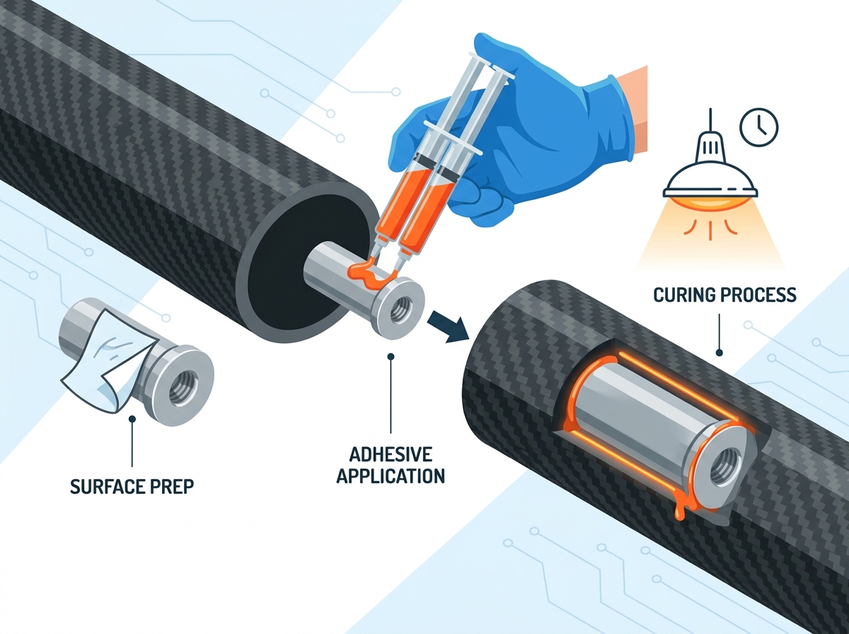
Choosing the right metal for the insert involves balancing weight, strength, cost, and galvanic compatibility. Aluminum (6061/7075) is lightweight and easily machined, but highly susceptible to galvanic corrosion when in contact with carbon fiber. It requires hard anodizing or a physical isolation barrier. Titanium offers an excellent strength-to-weight ratio, a lower thermal expansion coefficient closer to composites, and is galvanically compatible with carbon fiber. However, titanium incurs high material and machining costs, making it suitable primarily for high-end aerospace applications.
Designing the insert geometry to convert shear forces into compressive forces within the adhesive significantly improves joint strength. Features like diamond knurling, annular grooves, or ribbed undercuts increase the surface area and provide mechanical anchoring for the adhesive. These features prevent the insert from pulling out cleanly under high tensile loads, forcing the adhesive to fail cohesively rather than adhesively. We always specify a surface texture rather than bonding to a smooth turned finish.
Integrating flat flats, longitudinal escape grooves, or a central vent hole along the insert prevents trapped air from pushing the insert out or creating high-pressure void pockets. When pressing a tight-fitting insert into a closed tube, the trapped air acts like a piston, displacing the adhesive and creating dry spots. Proper venting ensures the adhesive remains uniformly distributed throughout the bond line.
Calculate the total volume of air that will be displaced during insertion.
Design a longitudinal groove or central through-hole with a cross-sectional area sufficient to vent this air without causing backpressure.
Ensure the vent path does not compromise the structural integrity of the insert under peak torsional loads.
Test the insertion process dry to verify that no pressure builds up before applying adhesive.
Engineering the insert's outer diameter to ensure a consistent 0.1mm to 0.25mm gap inside the carbon fiber tube is crucial for optimal adhesive performance. Utilizing centering features, integrated lands, or calibrated glass spacer beads in the adhesive maintains this precise gap. An adhesive layer that is too thin starves the joint, while a layer that is too thick reduces shear strength and increases weight. We measure every batch of tubes and adjust the insert machining tolerances accordingly.
Comparing adhesive chemistries based on shear strength, elongation at break, viscosity, and environmental resistance helps determine the best fit for specific drone applications. High shear strength is necessary for load-bearing joints, while elongation at break indicates the adhesive's ability to absorb impacts and vibrations. Viscosity affects how well the adhesive wets the surfaces and fills the bond line gap. You must match the adhesive properties to the specific flight dynamics of the airframe.
Toughened epoxies are the aerospace standard for bonding composites. They offer high tensile strength and rigidity, making them ideal for static loads and critical structural joints. However, they require precise mixing ratios, controlled clamping pressure, and longer cure times. The addition of toughening agents improves their impact resistance compared to standard brittle epoxies. We use these for primary structural nodes where maximum stiffness is required.
Methacrylate and acrylic adhesives provide faster curing times with high peel strength and flexibility. They are superior for absorbing high-frequency structural vibrations from drone rotors and handling impact loads during hard landings. While their absolute shear strength may be slightly lower than toughened epoxies, their dynamic performance often makes them a better choice for high-vibration UAV environments. They also require less stringent surface preparation, which speeds up assembly.
| Adhesive Type | Shear Strength | Vibration Resistance | Cure Time | Best Application |
|---|---|---|---|---|
| Toughened Epoxy | Very High | Moderate | 24-48 Hours | Primary structural nodes, static load bearing. |
| Methacrylate | High | Excellent | 1-2 Hours | Motor mounts, high-vibration areas. |
| Polyurethane | Moderate | Very High | 12-24 Hours | Secondary joints, high thermal expansion mismatch areas. |
Specifying and blending solid glass micro-beads, such as 120-micron diameter spheres, into the adhesive matrix prevents adhesive squeeze-out during assembly. These beads act as physical spacers, ensuring a minimum bond line thickness is maintained even under clamping pressure. This technique guarantees consistent adhesive volume and prevents dry joints caused by over-clamping. We mix these beads directly into the resin before adding the hardener.
Ensuring the chosen adhesive maintains its structural properties at the maximum operating temperature of the UAV is critical. The Glass Transition Temperature (Tg) is the point where the adhesive softens and loses its mechanical strength. Drones operating in hot climates or direct sunlight can experience high surface temperatures, requiring adhesives with a high Tg to avoid joint failure under load. Always select an adhesive with a Tg at least 20 degrees Celsius above your maximum expected operating temperature.
Addressing the reality that even premium aerospace adhesives will fail if applied to unprepared carbon fiber or oxidized metal is the foundation of reliable bonding. Surface preparation is the most critical step in the entire process. Contaminants, mold release agents, and weak oxide layers act as barriers, preventing the adhesive from forming strong chemical and mechanical bonds with the substrates. We spend more time on surface prep than on the actual bonding process.
Properly preparing the metal insert involves several steps to create a clean, active surface. First, degrease the part with volatile, non-residue solvents like Methyl Ethyl Ketone (MEK) or Acetone. Next, use mechanical abrasion, such as sandblasting with aluminum oxide media or Scotch-Brite, to increase the mechanical anchoring surface area. Finally, apply chemical etching, anodizing, or conversion coatings, like Alodine for aluminum, to stabilize the reactive oxide layer and prevent corrosion.
Solvent wipe the machined insert to remove cutting fluids.
Sandblast the bonding surface using 120-grit aluminum oxide at 40 PSI.
Blow off residual dust with clean, dry compressed air.
Apply a hard-coat anodize or chemical conversion coating immediately to prevent uncontrolled oxidation.
Store prepared inserts in sealed, desiccant-filled bags until ready for assembly.
Preparing the internal diameter of a carbon fiber tube requires specialized techniques. Removing internal mold release agents is essential, as peel ply is rarely an option for internal diameters of thin-walled tubes. Use internal abrasion methods like expandable hone brushes, rotary sanding mandrels, or precision abrasive sleeves to expose the raw carbon fibers. Follow this with strict solvent-wiping protocols, utilizing the white-rag test, to ensure a zero-contaminant, chemically active bonding surface.
For high-volume production, utilizing atmospheric plasma treatment or laser ablation provides automated, highly repeatable surface energy modification. These advanced techniques clean the surface at a molecular level and increase the surface energy, significantly improving adhesive wetting and bond strength without the variability of manual abrasion and solvent wiping. We implement plasma treatment when scaling up production to hundreds of units per week.
Implementing physical isolation barriers is necessary to prevent direct metal-to-carbon electrical pathways. When aluminum contacts carbon fiber in the presence of an electrolyte, galvanic corrosion rapidly degrades the aluminum. Use non-conductive fiberglass scrim sleeves, hard-coat anodizing, or specialized non-conductive epoxy films to isolate the metal insert from the carbon fiber tube, ensuring long-term joint durability. We never allow bare aluminum to touch raw carbon fiber under any circumstances.
Translating theoretical joint design into repeatable manufacturing processes requires strict adherence to assembly protocols. Controlling the environment, managing adhesive pot life, and ensuring consistent application techniques are crucial for minimizing variability between joints. A well-documented Standard Operating Procedure (SOP) is essential for achieving consistent aerospace-grade bonds. We calibrate our dispensing equipment daily to ensure accurate mix ratios.
Coating both the metal insert and the inner diameter of the tube ensures 100% surface wetting. Applying a helical bead of adhesive promotes even distribution as the insert is installed. This double-coating method prevents dry spots and ensures the adhesive fills the entire bond line gap, maximizing the contact area and joint strength. We use specialized pneumatic dispensers with long static mixing nozzles to reach deep into the tubes.
Utilizing a slow, continuous rotational insertion motion, or twisting, rather than a direct linear push forces air out and spreads the adhesive uniformly. This twisting action helps shear the adhesive, improving wetting and reducing the likelihood of trapped air bubbles. It also helps distribute the adhesive evenly across any mechanical interlocking features on the insert. We train our technicians to maintain a steady rotation until the insert bottoms out against the depth stop.
Designing dedicated assembly jigs to hold the insert perfectly concentric and axial within the tube during the initial gel phase prevents uneven bond lines. If the insert shifts during curing, the bond line will be thin on one side and thick on the other, creating stress concentrations and reducing overall joint strength. Proper fixturing ensures the engineered tolerances are maintained. We machine custom V-blocks and toggle clamps for every tube diameter we process.
Managing room temperature cures versus elevated temperature post-curing cycles maximizes the adhesive's cross-linking density and ultimate mechanical properties. While many adhesives cure at room temperature, a thermal post-cure often increases the Glass Transition Temperature (Tg) and overall shear strength. However, care must be taken to avoid warping the composite structure due to thermal expansion mismatches during the post-cure cycle. We use programmable ovens to ramp the temperature up slowly, hold it at the target, and then cool it down gradually.
Establishing testing protocols for production runs ensures every joint meets the required safety standards. Implementing a robust Quality Control (QC) system involves tracking adhesive batch numbers, monitoring cure temperatures, and performing regular sample testing. This traceability is essential for identifying the root cause of any failures and maintaining consistent manufacturing quality. We log the temperature and humidity of the bonding room for every batch produced.
Using ultrasonic thickness gauges, acoustic tap testing, or thermal imaging helps identify structural voids or localized delamination within the bond line without destroying the part. NDT methods are crucial for verifying the integrity of critical joints on finished drones. Acoustic tap testing is a simple but effective method for detecting large voids, while ultrasonic testing provides more detailed information about the bond line quality. We perform a 100% tap test on all primary structural joints before they leave the facility.
Conducting axial pull-out and torsional shear-to-failure tests on sample coupons or sacrificial parts validates the joint design and surface preparation process. Destructive testing provides quantifiable data on the ultimate strength of the joint. These tests should replicate the actual loading conditions the drone will experience in flight to ensure the safety factor is adequate. We pull at least one sample to failure from every production shift.
Classifying failures during destructive testing helps optimize the process. Adhesive failure, where separation occurs at the adhesive/substrate interface, indicates poor surface preparation. Cohesive failure, involving the physical splitting of the adhesive layer, indicates optimal surface preparation and joint design. Substrate failure, where the carbon fiber tube wall delaminates, indicates the joint strength exceeds the structural limit of the composite itself. We aim for cohesive or substrate failure in all our destructive tests.
Reliable metal-to-carbon fiber joints depend on more than selecting a high-strength adhesive. Insert geometry, surface preparation, bond line thickness, venting, material compatibility, and curing conditions must work together as a complete bonding system.
Toughened epoxies are well suited to highly loaded structural joints, while methacrylate adhesives may provide better impact and vibration tolerance. Regardless of chemistry, the metal and carbon fiber surfaces must be thoroughly cleaned and abraded, and the adhesive gap should remain controlled to prevent starvation or excessive bond thickness. Aluminum inserts also require electrical isolation from the carbon fiber to reduce galvanic corrosion.
Before production, engineers should validate the joint through pull-out, torsional, thermal, and vibration testing. A successful design should produce cohesive or substrate failure rather than separation at the bonded interface, confirming that the preparation and bonding process are reliable.
A: Toughened two-part epoxies are generally the best choice for high-strength structural joints due to their high shear strength and rigidity. For applications with high vibrations, methacrylate adhesives offer superior impact resistance and flexibility.
A: You must physically isolate the aluminum from the carbon fiber. This is achieved by hard-coat anodizing the aluminum insert, using a non-conductive fiberglass scrim layer, or applying a specialized non-conductive epoxy film barrier.
A: The optimal bond line thickness is typically between 0.1mm and 0.25mm. This gap ensures sufficient adhesive volume for strength while preventing the weakness associated with excessively thick adhesive layers. Glass micro-beads can help maintain this gap.
A: No, cutting threads directly into a carbon fiber tube severs the continuous fibers, severely compromising the structural integrity and load-bearing capacity of the tube. Metal inserts are required to distribute the fastener loads safely.
A: A vent hole prevents the piston effect, where trapped air compresses during insertion, pushing the insert back out or displacing the adhesive, which creates dry spots and weakens the joint.


