
English 
+86-157-6313-9515
lina@hezongmaterials.com
lina@hezongmaterials.com
26 Jiashan Road, Chucun Town, Weihai City, Shandong Province, China


Views: 0 Author: Site Editor Publish Time: 2026-07-02 Origin: Site


In UAV engineering, frame structural integrity dictates flight performance, payload capacity, and battery efficiency. The most critical structural components are the arms. Specifying the wrong dimensions leads to two costly extremes. Over-engineering adds dead weight that drastically reduces flight time. Under-engineering causes harmonic vibrations, poor PID tuning, or catastrophic mid-air failure under load. Selecting the optimal carbon fiber tube requires balancing outer diameter (OD), inner diameter (ID), and wall thickness against motor thrust, arm length, and mounting methods. This guide provides the engineering framework to evaluate and select the correct specifications for your specific UAV application.
Stiffness Scales with Diameter, Not Just Thickness: Increasing the outer diameter of a carbon fiber tube yields a higher stiffness-to-weight ratio than simply increasing wall thickness.
Wall Thickness Dictates Crush Resistance: While thin walls save weight, a minimum of 1.5mm to 2mm is typically required to withstand the clamping forces of motor mounts and frame brackets without crushing.
Internal Routing Requires ID Planning: The inner diameter must accommodate the AWG wire size of motor phases and potential ESC placement while maintaining sufficient wall thickness.
Manufacturing Method Matters: Roll-wrapped tubes with multi-directional fiber orientation offer superior torsional rigidity for drone arms compared to cheaper pultruded alternatives.
You must define the arm as a cantilever beam subjected to upward thrust at the motor end. Deflection alters motor angles, leading to thrust vectoring errors and overworked flight controllers. The structural engineering math relies on the deflection formula for a cantilever beam with an end load. Deflection equals the load multiplied by the length cubed, divided by three times the material Young's Modulus and the Area Moment of Inertia. Your primary goal is achieving near-zero deflection at maximum motor thrust while minimizing mass. When building heavy-lift platforms, even a two-degree deflection at the motor mount translates to massive efficiency losses. The flight controller constantly fights to maintain level flight, draining the battery prematurely.
Large propellers exert significant rotational forces during rapid RPM changes for yaw authority and gyroscopic precession. The Polar Moment of Inertia for hollow circular sections dictates how well the arm resists these forces. It is calculated using the outer and inner diameters. A carbon fiber tube must resist twisting to maintain precise yaw control. If the arm twists, motor mount slippage occurs, degrading flight stability immediately. We see this frequently on X8 coaxial builds where the torque from two counter-rotating motors on a single arm creates immense twisting forces. You need a tube that locks those motors in perfect alignment.
Tube stiffness, mass, and natural frequency share a direct relationship. Flexible arms transmit motor vibrations directly to the gyro. This requires heavy software filtering within the flight controller. Excessive filtering introduces latency and reduces overall flight stability. Stiff arms push the natural frequency above the motor vibration spectrum, ensuring clean gyro data. When you tune a drone with rigid arms, you can push the PID gains much higher without inducing oscillations. This results in a locked-in flight feel that professional operators demand.
You must differentiate between static thrust limits and dynamic flight conditions. Load factor calculations determine design safety margins. Industrial drones typically require margins for 3G to 5G maneuvers. Racing or freestyle quads often experience loads exceeding 10G. Designing only for static hover will result in mid-air structural failure during aggressive maneuvers or wind gusts. Consider a 20kg agricultural sprayer hitting the end of a field and banking hard to turn. The G-forces multiply the effective weight on those outer arms exponentially. Your tube selection must account for these dynamic spikes.
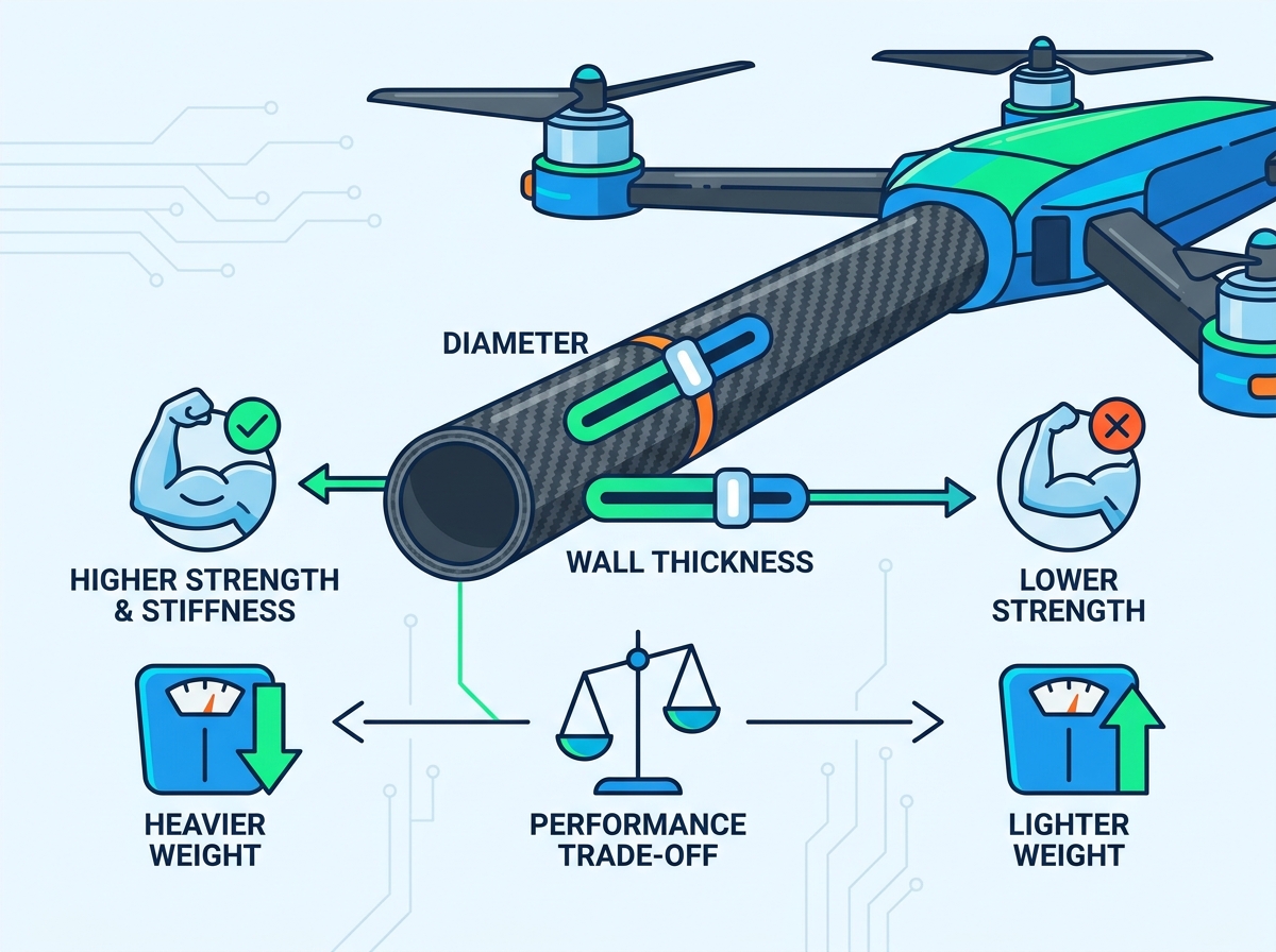
Bending stiffness increases to the fourth power of the outer diameter for a given wall thickness. This mathematical reality makes a larger OD the most weight-efficient way to increase rigidity. However, you must balance this against aerodynamic drag. Larger OD tubes increase drag in high-speed forward flight. Conversely, they minimize vertical downwash losses in hovering applications. If you upgrade from a 16mm to a 25mm tube, you gain massive stiffness with only a marginal weight penalty, provided you keep the wall thickness reasonable.
Routing 3-phase motor wires internally reduces drag and protects against prop strikes. You must outline the spatial requirements carefully. Determine the required ID based on wire gauge and insulation thickness. For example, the tube must accommodate three silicone-insulated wires without pinching. Leave adequate clearance to prevent wire chafing during flight vibrations. If you run 12 AWG wire for high-amp motors, a 10mm ID tube will be too tight once you account for the wire twists and bullet connectors.
Round tubes offer isotropic torsional strength and make adjusting alignment angles easy. They do require precision clamping systems to prevent rotation. Square or rectangular tubes simplify mounting with flat mating surfaces. They completely eliminate motor twist but exhibit poorer torsional performance-to-weight ratios. Aerodynamic teardrop profiles minimize motor downwash drag. However, they introduce complex, proprietary clamping and mounting hardware challenges. Most custom builders stick to round tubes because the hardware ecosystem is vast and standardized.
| Drone Class | Typical Payload / Weight | Recommended Outer Diameter (OD) | Typical Wall Thickness |
|---|---|---|---|
| Cinewhoops / Light Quads | Sub-1kg | 10mm – 12mm | 1.0mm |
| Medium Lift / Cinelifters | 1kg – 5kg | 16mm – 22mm | 1.5mm |
| Heavy Lift / Agricultural | 10kg+ | 25mm – 40mm | 2.0mm - 3.0mm |
Excessively thick walls offer diminishing returns on bending stiffness. Meanwhile, they cause a linear increase in overall weight. Wall thickness should be driven primarily by localized stress points rather than overall span stiffness. Analyze the forces at the mounting points to determine the minimum required thickness. Adding an extra millimeter of carbon along a 500mm arm adds significant weight. You are better off using a larger OD with a thinner wall for span stiffness, only increasing wall thickness if crush resistance demands it.
Evaluate the compressive forces exerted by CNC aluminum motor mounts and frame clamps. A 1mm wall thickness often fails under clamping pressure. Therefore, 1.5mm to 2.5mm serves as the industry standard for clamped drone arms. Keep M3 or M4 mounting screws within safe torque values based on the specific wall thickness to prevent structural crushing. We recommend using a torque driver set to 0.6 Nm for M3 bolts on 1.5mm wall tubes. Anything higher risks fracturing the epoxy matrix beneath the clamp.
Assess the tube's ability to survive hard landings and lateral impacts. Thicker walls prevent localized fiber buckling during crash scenarios. They also mitigate micro-cracking and delamination. A slightly thicker wall at the motor mount drastically improves the long-term survivability of the airframe. When a drone clips a branch, the impact force travels down the arm. A thin-walled tube will shatter at the point of impact, whereas a 2mm wall tube will often bounce off and sustain only superficial scratches.
Pultruded tubes feature unidirectional longitudinal fibers. They offer high bending stiffness but zero torsional strength and are highly prone to splitting. Roll-wrapped tubes utilize multi-directional layers, providing high torsional rigidity. A roll-wrapped carbon fiber tube for drone arms is the mandatory engineering standard for reliable flight. Never use pultruded tubes for multirotor arms. The moment a motor applies torque, a pultruded tube will split down the middle, dropping your rig out of the sky.
Longitudinal fibers at 0° handle bending loads effectively. Fibers oriented at 90° and ±45° handle hoop strength and torsion. The optimal layer composition mix for drone arms alternates 0°/90° and ±45° plies. This balanced structural performance ensures the arm can handle complex dynamic flight loads without failing. A standard 3K twill weave on the exterior provides excellent containment for the unidirectional layers beneath, preventing them from peeling back if the surface gets scratched.
Standard industrial grade T300 offers adequate performance for basic applications. High-strength T700 provides superior tensile strength. High-modulus fibers like M40J or M46J offer maximum stiffness but are brittle. T700 is widely considered the sweet spot for structural integrity and cost-efficiency in high-performance drone designs. High-modulus tubes are great for static structures, but they shatter easily under the dynamic impacts common in drone operations.
The epoxy resin matrix binds the carbon fibers together and transfers loads between them. The Glass Transition Temperature of the resin has structural implications. Arms subjected to heat generated by high-power motors can soften if the resin's thermal limits are exceeded. Select high-temperature resins for heavy-lift applications. If you mount a massive 100KV motor directly to a carbon tube and run it at full throttle for 20 minutes, the heat transfer can actually delaminate cheap resin systems.
Matte finishes provide better friction for clamping mechanisms than glossy finishes. Strict OD tolerances, such as +/- 0.1mm, are mandatory. They ensure a secure, slip-free fit in standardized aluminum clamps. Poor tolerances lead to loose arms and severe flight instability. If your tube measures 24.8mm and your clamp is machined for exactly 25.0mm, you will never get a secure grip without crushing the tube or shimming it with tape.
Drilling holes directly through carbon fiber severs continuous fibers. This creates severe stress concentration points that lead to premature failure. Advocate for friction-based clamping mechanisms over through-bolt designs to maintain tube strength. If drilling is unavoidable, use metal sleeves, grommets, or structural foam inserts to prevent wall collapse. When you drill a 3mm hole in a 16mm tube, you instantly reduce its load-bearing capacity by a massive margin. Always clamp, never drill.
An electrochemical reaction occurs between carbon fiber and aluminum mounts in humid, wet, or marine environments. This galvanic corrosion degrades the aluminum hardware rapidly. Provide mitigation steps such as using anodized aluminum. You can also apply fiberglass isolation layers or dielectric barrier coatings to separate the materials. A simple layer of Kapton tape between the carbon tube and the raw aluminum clamp completely stops the galvanic circuit.
Outline a rigorous testing protocol for incoming material. Verify concentricity across the entire length of the tube. Measure deflection with static weights to confirm stiffness ratings. Inspect the cut ends for internal resin voids or fiber misalignment before assembling the drone frame. We recommend setting up a simple jig on your workbench.
Clamp one end of the tube securely to the bench.
Hang a known weight (e.g., 5kg) from the opposite end.
Measure the deflection with a digital caliper.
Compare this measurement against your baseline requirements.
Choosing the right carbon fiber tube for drone arms requires more than selecting a standard outer diameter or wall thickness. The specification should be based on the drone’s maximum thrust, arm length, payload, dynamic load factor, mounting method, and internal wiring requirements.
In most designs, increasing the outer diameter is a more weight-efficient way to improve bending stiffness than simply increasing wall thickness. Wall thickness should then be selected to provide sufficient crush resistance around motor mounts and frame clamps, with 1.5–2.0 mm serving as a common starting range for many medium- and heavy-lift clamped structures rather than a universal requirement.
For reliable flight performance, prioritize roll-wrapped tubes with a balanced fiber layup that can resist both bending and torsional loads. Use properly fitted clamping hardware, avoid drilling through load-bearing fibers whenever possible, and confirm dimensional tolerances before assembly.
Before placing a full production order, test sample tubes under realistic clamping, deflection, vibration, and load conditions. A properly validated tube specification can reduce structural weight, improve PID tuning, protect internal wiring, and minimize the risk of arm deformation or failure during flight.
A: The best choice is a roll-wrapped, 3K twill or matte finish tube. It should feature a balanced 0/90 and ±45-degree layup to handle both bending and torsional loads effectively.
A: A wall thickness of 1.5mm to 2.0mm is standard for medium-to-heavy lift drones to prevent crushing at the motor mounts. Sub-250g drones can safely use 1mm or less.
A: Avoid drilling holes whenever possible. Drilling cuts load-bearing fibers and creates severe stress risers. Friction clamps are highly recommended to preserve structural integrity.
A: Splitting is common in cheap pultruded tubes that lack hoop strength. It is also frequently caused by over-tightening aluminum clamps on thin-walled tubes.
A: Yes, a larger diameter increases bending stiffness significantly. This raises the natural frequency of the arm, preventing motor vibrations from reaching the flight controller gyro.


