
English 
+86-157-6313-9515
lina@hezongmaterials.com
lina@hezongmaterials.com
26 Jiashan Road, Chucun Town, Weihai City, Shandong Province, China


Views: 0 Author: Site Editor Publish Time: 2026-07-13 Origin: Site


Frame geometry dictates the upper limits of UAV performance, directly influencing payload capacity, flight time, and sensor stability. When engineering a multi-rotor or fixed-wing VTOL platform, structural architecture drives the entire design process. Selecting the wrong structural profile results in parasitic drag, catastrophic failure under torsional loads, or excessive manufacturing complexity during assembly. Engineers must balance weight, rigidity, and aerodynamic efficiency to build a reliable platform capable of handling dynamic flight loads.
A comparative engineering analysis of round versus square profiles evaluates structural mechanics, aerodynamic penalties, and integration realities to determine the optimal architecture for specific UAV applications. Understanding these trade-offs ensures you select the right carbon fiber tube for your exact operational requirements. We will examine the physical properties, assembly constraints, and material science principles that govern composite frame design.
Torsional Superiority: Round profiles offer superior torsional rigidity and lower aerodynamic drag, making them ideal for multi-rotor arms subjected to high rotational forces.
Assembly Efficiency: Square profiles provide higher bending stiffness on a single axis and eliminate alignment issues, significantly reducing assembly time for heavy-lift and industrial platforms.
Weight Penalties: Square profiles inherently carry a weight penalty due to thicker corner layups and resin pooling required to prevent stress concentrations.
Clamping Risks: Both profiles require specific mitigation strategies against crush forces at motor mounts and frame joints, dictating hardware selection.
A drone frame must withstand complex dynamic forces during flight. The primary forces acting on a frame include bending moments generated by payload weight and thrust, alongside torsional loads induced by motor torque and rapid yaw maneuvers. Multi-rotor arms act as cantilever beams, requiring high stiffness to prevent flex that can confuse flight controller gyroscopes. When an arm flexes, the motor thrust vector shifts, forcing the flight controller to constantly compensate, which degrades flight stability and wastes battery power.
Carbon composites are anisotropic, meaning their strength varies depending on fiber orientation. This differs from isotropic materials like aluminum, which exhibit uniform strength in all directions. Engineers must leverage this anisotropy to maximize the stiffness-to-weight ratio, placing fibers exactly where load paths demand them. For example, unidirectional fibers running lengthwise handle bending loads, while fibers oriented at 45 degrees handle torsional twisting.
The raw fiber precursor dictates the ultimate tensile strength of the structure. Standard Toray T700 fibers offer excellent baseline performance, but intermediate-modulus fibers like Toray T800 provide higher tensile strength for demanding aerospace applications. The choice of fiber directly influences the tube's ability to resist deformation under load. High-modulus fibers are stiffer but can be more brittle, requiring careful consideration of impact resistance.
Matrix chemistry is equally important. High glass transition temperature (Tg) epoxy resins are necessary to prevent structural softening. Brushless motors generate significant heat, which transfers directly to the motor mounts and arms. A high-Tg resin ensures the composite matrix remains rigid under thermal stress, preventing the arm from warping mid-flight.
Fiber Volume Fraction (Vf) determines the ratio of carbon fiber to epoxy resin. A true drone-grade carbon fiber tube requires a Vf of at least 60%. This high fiber density minimizes excess resin weight, maximizing the structural efficiency of the component. Excess resin adds dead weight without contributing to the structural strength.
Aerodynamic drag significantly impacts flight efficiency. Acceptable drag coefficients (Cd) vary depending on the flight regime. Forward flight demands streamlined profiles to reduce frontal area drag, while hovering requires managing prop-wash turbulence pushing down on the frame arms. The shape of the arm dictates how air flows around it, directly affecting the lift-to-drag ratio of the entire aircraft.
The cross-sectional area directly affects wind resistance. Larger profiles catch more wind, forcing the flight controller PID loops to work harder to maintain stability. This constant compensation draws higher current from the ESCs, reducing overall battery life and flight time. Minimizing the frontal area of the frame arms is a primary objective in high-efficiency drone design.
Cylindrical structures excel at handling torsional loads due to their uniform polar moment of inertia. When a twisting force is applied, the shear stress distributes evenly across the entire circular cross-section. This geometry prevents localized stress concentrations that cause premature failure in angular profiles. The continuous curve of a round tube means there are no weak points where stress can accumulate.
High-torque brushless motors generate intense twisting forces during rapid acceleration and deceleration. A round profile resists these forces exceptionally well. Roll-wrapped layup schedules further enhance this capability by integrating ±45° angle plies. These angled fibers specifically target torsional modulus, locking the tube against twist. A well-designed roll-wrapped tube will have a specific sequence of unidirectional and angled plies to balance bending and torsional stiffness.
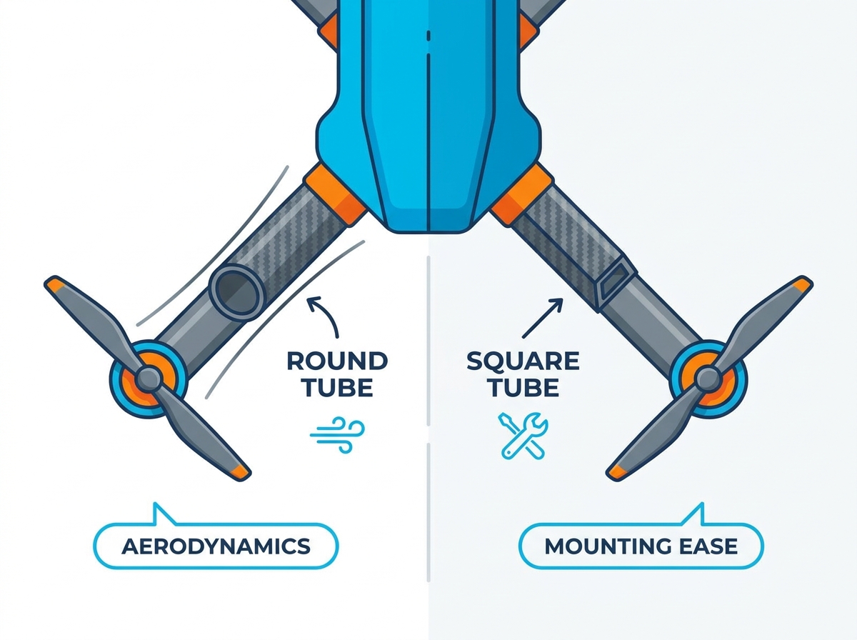
Airflow disruption is a major factor in multi-rotor efficiency. A cylindrical profile presents a relatively low drag coefficient (Cd ≈ 1.2). In contrast, a flat-faced square profile creates significant turbulence (Cd ≈ 2.05). This difference is notable both in forward flight and when managing downward prop-wash. The smooth surface of a round tube allows air to detach cleanly, reducing the wake turbulence behind the arm.
Reduced drag translates directly to improved performance. Lower aerodynamic resistance means motors draw less power to maintain altitude or forward speed. This efficiency gain improves battery life, extends flight times, and reduces thermal load on the propulsion system. For long-endurance mapping drones, minimizing drag on the frame arms can add several minutes to the total flight time.
The primary drawback of round tubes is the mechanical difficulty of achieving perfect motor-to-frame alignment. Setting a precise zero-degree roll axis requires meticulous calibration during assembly. Without flat reference surfaces, technicians must rely on jigs and digital inclinometers. If a motor is slightly tilted, it introduces a constant yaw tendency that the flight controller must fight.
Precision-machined boom clamps are absolutely necessary. If a clamp is improperly secured, the boom can rotate under high-yaw maneuvers. This catastrophic failure instantly destabilizes the aircraft. Engineers must design robust clamping mechanisms to prevent any rotational slip. Common solutions include using friction paste, pinning the tube, or designing clamps with high surface area contact.
Square profiles offer superior resistance to bending along their primary vertical and horizontal axes. The area moment of inertia is concentrated further from the neutral axis compared to a round tube of similar dimensions. This geometry excels at supporting heavy vertical loads. The flat top and bottom surfaces act like the flanges of an I-beam, resisting the tension and compression forces generated by bending.
Agricultural spraying drones, heavy-lift cinema rigs, and cargo platforms benefit immensely from this architecture. In these applications, vertical load-bearing capacity and cantilever stiffness are paramount. The square profile minimizes vertical deflection under heavy payload stress. A rigid frame ensures that the payload remains stable and that the flight controller receives accurate sensor data.
Flat surfaces revolutionize the assembly process. They eliminate the need for complex, heavy clamping mechanisms required for round tubes. Components like ESCs, motors, and landing gear can be mounted directly to the flat faces using simple hardware. This direct mounting approach saves weight and reduces the overall part count of the frame assembly.
This inherent self-alignment drastically reduces bench assembly time. Field repairs become significantly less complex, as technicians do not need specialized alignment jigs to replace a damaged arm. The flat geometry guarantees the motor mount sits perfectly level relative to the frame. This plug-and-play nature is highly valued in industrial operations where downtime must be minimized.
Manufacturing square profiles via pultrusion or bladder molding introduces specific challenges. Resin pooling and fiber distortion inevitably occur at the 90-degree corners. To compensate for these stress concentrations, manufacturers must add extra material to the corners. This added material ensures the corners do not split under load.
This requirement results in a weight penalty. A square profile will typically weigh more than a round profile of equivalent cross-sectional area and bending stiffness. Furthermore, internal corner radii specifications are critical. Sharp internal corners create massive stress concentrations, leading to longitudinal splitting under heavy load. A generous internal radius is required to distribute the stress smoothly.
| Property | Round Profile | Square Profile |
|---|---|---|
| Torsional Rigidity | Excellent (Uniform shear distribution) | Moderate (Stress concentrates at corners) |
| Aerodynamic Drag (Cd) | Low (~1.2) | High (~2.05) |
| Bending Stiffness (Vertical) | Good | Excellent (Higher area moment of inertia) |
| Assembly Alignment | Difficult (Requires jigs/inclinometers) | Simple (Self-aligning flat surfaces) |
| Weight Efficiency | High (No corner resin pooling) | Lower (Requires reinforced corners) |
Not all composites are created equal. Standard commercial tubing often contains high void contents and poor dimensional tolerances. A true aerospace-grade component demands strict quality metrics, such as a void content below 1% and outer diameter tolerances of ±0.05mm. Voids act as stress risers and significantly reduce the interlaminar shear strength of the tube.
Availability and cost-scaling differ between profiles. High-modulus round stock is widely available and benefits from economies of scale in roll-wrapping production. Square stock often requires specialized mandrels and longer lead times, impacting procurement schedules for large-scale manufacturing. Engineers must factor these supply chain realities into their design decisions.
Engineers must rely on standardized testing to validate structural components. Critical ASTM testing standards include ASTM D3039 for tensile properties and ASTM D2344 for short-beam shear strength. These tests provide empirical data on material limits. Physical testing is the only way to verify that a composite structure will perform as designed under real-world loads.
Evaluating manufacturer-provided material data sheets (MDS) is essential. Engineers must verify that the tested properties align with the operational loads of the drone. Compliance with these standards is often required for drone airworthiness certifications and commercial deployment. A rigorous testing protocol ensures the safety and reliability of the final product.
High-frequency motor vibrations wreak havoc on flight controller IMUs and optical payloads. Round and square geometries transmit these vibrations differently. The uniform stiffness of a round tube often provides more predictable resonance frequencies, while square tubes can exhibit complex harmonic modes. Unpredictable resonance can cause the flight controller to overreact, leading to oscillations in flight.
Fiber layup orientation plays a major role in tuning resonance. Unidirectional cores provide longitudinal stiffness, while 3K twill outer weaves help dampen high-frequency vibrations. Engineers must specify the correct layup to isolate sensitive electronics from propulsion noise. Adding vibration isolation mounts between the frame and the flight controller is also a standard practice.
Carbon fiber is electrically conductive and highly noble. When it comes into direct contact with aluminum, steel, or titanium fasteners in a humid environment, galvanic corrosion occurs. This process rapidly degrades the metal components, leading to joint failure. The carbon fiber acts as the cathode, while the metal acts as the anode, sacrificing itself in the corrosive reaction.
Mitigation methods are mandatory. Engineers must use non-conductive glass fiber isolation layers (scrim plies) during manufacturing, or utilize nylon washers and specialized primers during assembly. Isolating the carbon composite from dissimilar metals ensures long-term structural integrity. Anodizing aluminum components provides some protection, but physical isolation is the most reliable method.
Applying high torque to mounting fasteners risks localized compressive failure. Carbon composites possess high tensile strength but are susceptible to crushing forces. Over-tightening clamps will crush the matrix and cause delamination. Once the matrix is crushed, the structural integrity of the tube is permanently compromised.
Mitigation tactics require careful hardware design. Internal aluminum or 3D-printed composite bulkheads can support the tube from the inside. Specialized saddle clamps distribute the load for round profiles, while load-spreading backing plates are necessary for square profiles. Designing clamps that apply even pressure over a large surface area is the key to preventing crush damage.
Drilling through-holes in carbon composites severs continuous load-bearing fibers, severely compromising structural integrity. It creates stress risers that can initiate catastrophic cracks under flight loads. A hole drilled through a carbon tube acts as a starting point for longitudinal splitting.
If drilling is unavoidable, industrial best practices must be followed. Use high-RPM, carbide or diamond-coated brad-point drills. Always use backing boards to prevent breakout on the exit hole, and employ wet drilling techniques for dust mitigation. However, alternatives like external friction clamping or structural bonding are strongly recommended to maintain the integrity of the continuous fibers.
Permanently bonding carbon-to-carbon or carbon-to-metal joints requires aerospace-grade structural adhesives, such as Scotch-Weld DP420 or DP460. These toughened epoxies provide immense shear strength and resist vibration fatigue. A properly bonded joint can be stronger than the composite material itself.
Surface preparation is the most critical step. The process demands solvent degreasing, mechanical abrasion to remove mold release agents, and a water-break-free test to confirm a pristine surface. Proper preparation ensures maximum adhesion and joint reliability. Skipping surface preparation will result in a weak bond that will fail under load.
Degrease the surface using isopropyl alcohol or acetone to remove surface contaminants.
Abrade the bonding area using 120-grit sandpaper or a Scotch-Brite pad to remove the glossy resin layer.
Perform a water-break-free test to ensure the surface is completely clean and ready for adhesive application.
Apply the structural adhesive evenly and clamp the joint securely while the epoxy cures.
Choosing between round and square carbon fiber tubes requires balancing torsional rigidity, bending stiffness, aerodynamic efficiency, assembly complexity, and weight.
Round tubes are generally better suited to high-speed or highly maneuverable multirotor platforms because their circular geometry distributes torsional stress evenly and reduces aerodynamic resistance. However, they require carefully designed clamps and alignment controls to prevent arm or motor-mount rotation.
Square tubes provide flat mounting surfaces, predictable component alignment, and strong bending resistance along their primary axes. These advantages make them practical for heavy-lift, agricultural, cargo, and other industrial drones where assembly efficiency and vertical load capacity are more important than minimum drag.
Neither profile is universally superior. Engineers should select the geometry according to the drone’s dominant load direction, flight regime, mounting method, repair requirements, and production constraints. Before finalizing the frame, validate the selected profile through bending, torsion, vibration, clamping, and joint testing under realistic motor thrust and payload conditions.
A: Round tubes are generally lighter for a given torsional strength due to the lack of thickened corners and excess resin required in square profiles.
A: While possible with specialized carbide or diamond tooling, drilling severs continuous fibers and creates stress risers; external clamping or structural bonding is preferred.
A: Use keyed clamps, friction-enhancing carbon assembly pastes, pinning techniques with roll pins, or split-clamp assemblies to secure motor mounts.
A: Square tubes often carry a premium due to the more complex mandrel removal, mold wear, and lower production volumes compared to standard round roll-wrapped tubes.
A: Thickness depends on the specific payload and tube diameter, but heavy-lift platforms typically utilize 1.5mm to 2.5mm wall thicknesses with optimized multi-directional layups.
A: Surface finish is primarily cosmetic, though matte or textured finishes can offer significantly better friction coefficients for clamping mechanisms.


