
English 
+86-157-6313-9515
lina@hezongmaterials.com
lina@hezongmaterials.com
26 Jiashan Road, Chucun Town, Weihai City, Shandong Province, China


Views: 0 Author: Site Editor Publish Time: 2026-10-11 Origin: Site


Composite engineering presents a fascinating paradox for modern design teams. We rely entirely on these advanced structures to achieve unmatched strength-to-weight ratios. However, standard mechanical fasteners often cause catastrophic localized core crushing during assembly. You cannot simply drive a bolt into a hollow cell. Successfully integrating these panels into a broader structural assembly requires highly specialized mounting hardware. It also demands precise cavity preparation and meticulously calculated load distribution.
This comprehensive guide outlines the technical realities of potted inserts and edge closeouts. We explore the strict machining tolerances necessary for reliable component integration. Our objective is to help engineering and procurement teams navigate these specific manufacturing challenges. You will learn how to transition seamlessly from fragile prototype designs to scalable, reliable production assemblies. By understanding these core principles, you can prevent structural failures and optimize your manufacturing workflows.
Direct fastening into honeycomb cores inevitably leads to structural failure; localized loads must be distributed to the carbon fiber skins.
Potted inserts (blind or through-hole) are the industry standard for handling high pull-out and shear loads.
Edge closeouts serve a dual purpose: providing structural mounting points and sealing the core against environmental ingress.
Precision carbon fiber cutting and cavity routing are non-negotiable prerequisites for void-free adhesive bonding.
Sourcing pre-machined custom carbon fiber components with factory-installed inserts reduces assembly bottlenecks and ensures reliable quality control.
Mounting hardware introduces intense point loads into composite structures. Standard bolts concentrate stress directly on the fragile honeycomb walls. This concentrated pressure quickly leads to skin delamination. It also causes severe localized compression failure. You must rethink how forces travel through these materials. A successful mounting strategy avoids core loading entirely. Instead, it transfers point loads outward. Proper hardware distributes this stress evenly across the rigid upper and lower carbon fiber face sheets.
Engineers evaluate carbon fiber honeycomb sandwich panels based on highly specific success criteria. The composite skins handle tension and compression beautifully. The honeycomb core merely separates these skins to increase the moment of inertia. Therefore, all shear, tension, and compression forces from fasteners must route directly into those skins.
You must apply a strict evaluation lens during the design phase. Designers must accurately calculate all anticipated load types. Static loads require different hardware profiles than dynamic or vibrational loads. A vibrating drone chassis behaves differently than a static architectural panel. These calculations directly dictate your hardware requirements.
Insert Size: Larger diameters spread loads over wider skin areas.
Flange Diameter: Wider flanges offer superior resistance against pull-through failures.
Potting Volume: The amount of epoxy used determines the ultimate shear strength of the anchor point.
Panel Thickness: Deeper cores allow for longer inserts, dramatically increasing tension limits.
You must finalize these metrics early in the CAD phase. Failing to anticipate dynamic vibrational loads often results in hardware tearing loose during field operations. We recommend modeling these load paths using finite element analysis (FEA) before ordering prototype hardware.
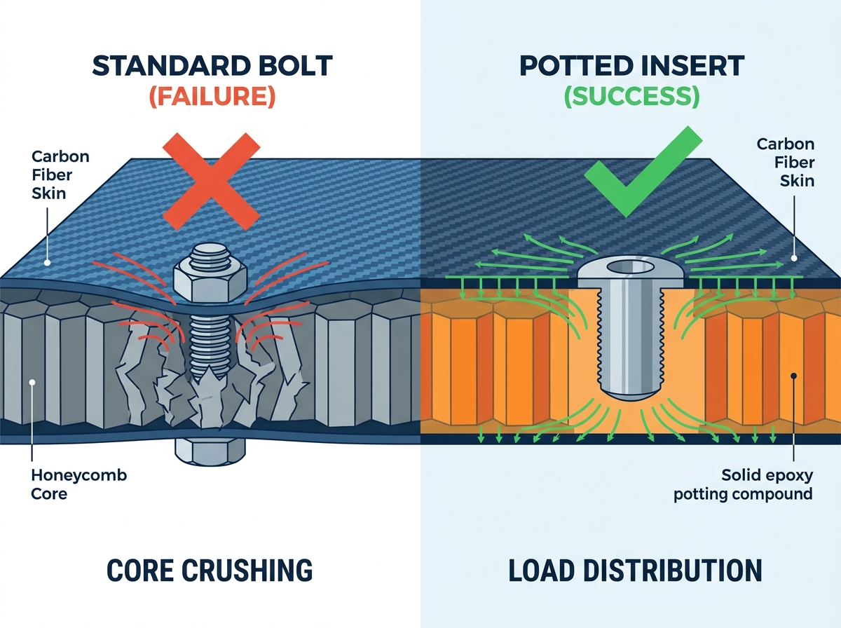
Potted inserts represent the aerospace industry standard for composite fastening. They bridge the mechanical gap between a threaded fastener and the hollow core. Choosing the correct solution category is critical for long-term assembly survival.
Engineers typically choose between three primary insert designs. Blind inserts work best when assembly access is restricted to only one side of the panel. We frequently use them for standoff mounting. They also excel at lightweight component attachment where rear access is impossible. Through-hole inserts span the entire total thickness of the panel. They offer superior performance for high-torque applications. You should specify through-hole designs for primary structural joining and high compression loads. Floating inserts feature a mechanically separate internal thread. They allow for slight misalignment during final assembly. This feature drastically reduces tolerance stacking issues across large structures.
Potted Insert Comparison Guide
Insert Type | Primary Application | Load Capacity | Installation Access |
|---|---|---|---|
Blind Insert | Lightweight attachments, standoffs | Moderate (Shear/Tension) | Single-sided |
Through-Hole | Structural joining, high torque | Maximum (Compression/Shear) | Dual-sided preferred |
Floating Insert | Complex assemblies, multi-point mounting | Moderate | Single or Dual-sided |
The physical potting process requires extreme precision. Technicians inject structural epoxy into the machined core cavity around the insert. The adhesive flows into the surrounding honeycomb cells. It cures to form a solid, immovable load-bearing anchor. However, this process introduces significant quality risks. Incomplete adhesive fills leave hidden internal voids. These air pockets drastically reduce pull-out strength. Conversely, over-filling the cavity adds unnecessary weight. It also risks adhesive spilling onto the cosmetic face sheets.
You must also mitigate galvanic corrosion vigorously. Carbon fiber conducts electricity efficiently. It behaves similarly to a noble metal in the galvanic series. If you place a standard zinc-plated steel insert inside the panel, it will corrode rapidly. Moisture acts as an electrolyte, accelerating this degradation. To prevent galvanic failure, you must specify titanium, stainless steel, or hard-anodized aluminum inserts. These materials safely contact carbon fiber without triggering destructive electrochemical reactions.
Raw composite panels arrive containing exposed edges. You can easily see the open honeycomb cells along the perimeter. Leaving these edges open invites structural and environmental failures. Edge closeouts become strictly required when panels mount via their perimeter perimeters. Slotted frames and clamping tracks require solid edges to prevent crushing. Furthermore, open cores easily trap moisture, harsh chemicals, and factory debris.
Water ingress poses a severe threat to aerospace and marine components. Trapped water undergoes freeze-thaw cycles. Expanding ice rapidly rips the carbon skins away from the core. Proper edge sealing completely neutralizes this risk.
Manufacturers utilize several distinct approaches to seal panel perimeters. Each method balances weight, strength, and production complexity.
Potted Edges (Liquid Epoxy): Technicians route out the core material along the perimeter. They fill this empty channel using a syntactic potting compound. This method remains highly customizable for complex shapes. However, it is heavily labor-intensive.
C-Channel / U-Profile Bonding: Manufacturers cap the raw edge using a pre-formed carbon fiber or aluminum channel. Structural adhesive secures the cap in place. This approach provides excellent high-impact edge protection. It effectively shields panels from blunt force strikes.
Solid Edge Framing: This method happens during the initial panel manufacturing phase. Builders replace the perimeter core with high-density foam or solid composites prior to laminating the skins. It creates a seamless, incredibly strong border.
Your team must use a precise decision matrix here. Compare the weight penalty of solid epoxy potting against your payload limits. Contrast this against the manufacturing complexity of pre-laminated solid edges. If your panel features highly irregular curved borders, potted liquid epoxy usually offers the most practical path forward. For straight, rectangular panels, C-channel caps provide superior durability for less labor.
Proper insert installation hinges on surgically precise core removal. This machining bottleneck ruins many novice composite projects. You must hollow out the honeycomb core without damaging the opposing face sheet. Standard metalworking tools fail miserably here. Standard drill bits inevitably cause skin delamination. They aggressively grab and tear the fragile aluminum or Nomex core ribbons.
Precision carbon fiber cutting demands specialized tooling. We strictly require diamond-coated routers. These abrasive tools grind away the tough carbon fibers smoothly. Once you breach the top skin, you must use specialized undercut tools. These tools feature a wider cutting head mounted on a narrow shaft. They reach inside the hole and carve away the core material horizontally. This creates a larger internal cavern for the potting epoxy while keeping the surface hole small.
Machining the cavity is only the first step. Structural epoxy bonds rely completely on pristine surface conditions. A contaminated cavity guarantees adhesive failure under load.
Debris Extraction: Vacuum all dust, loose carbon splinters, and torn core ribbons from the cavity completely.
Solvent Flushing: Inject a controlled amount of high-purity isopropyl alcohol to dissolve any residual cutting fluids or oils.
Surface Abrasion: Lightly abrade the inner surface of the carbon skin using a specialized micro-brush to increase mechanical grip.
Flash Evaporation: Allow the cavity to dry completely. Trapped solvent vapors will create fatal voids in the curing epoxy.
Scale and compliance heavily dictate your machining strategy. Manual routing is highly prone to human error. A tired technician might easily drill straight through the bottom face sheet. CNC-machined cavities are absolutely required for repeatable, aerospace-grade tolerances. Automated milling centers control depth to the fraction of a millimeter. They ensure your undercut profiles remain perfectly consistent across hundreds of mounting points.
Scaling up production introduces the classic build versus buy dilemma. Modifying standard off-the-shelf panels in-house carries steep hidden penalties. You face exceptionally high labor costs. Routing composite materials generates hazardous, electrically conductive dust. Your facility requires strict OSHA-compliant dust mitigation systems. Furthermore, manual installation processes often yield unacceptably high scrap rates. One misaligned insert ruins an expensive panel.
Procuring fully finished custom carbon fiber components shifts these burdens away from your floor. Specialized composite manufacturers already possess the tooling and environmental controls necessary for flawless execution. When evaluating potential manufacturing partners, apply rigorous shortlisting logic.
First, verify their exact tolerance capabilities. Ask if the supplier can CNC machine cavities and pot inserts to tight positional tolerances. A misaligned insert by even two millimeters will completely stall your final assembly line. Second, audit their testing and QA protocols. Reputable suppliers utilize ultrasonic non-destructive testing. They perform acoustic tap-testing to verify void-free insert potting objectively. They test batch coupons for ultimate shear and pull-out strength.
Finally, calculate the true turnkey value. Specifying complete panels delivered cut to shape with inserts and edge closeouts pre-installed streamlines your final assembly line massively. Your workers simply unbox the panel and bolt it into place. This strategy drastically reduces internal bottlenecks. It safely shifts production liability to the manufacturer. If an insert pulls out during QA, the supplier absorbs the replacement burden, not your procurement budget.
Reliable mounting of carbon fiber honeycomb panels relies entirely on intelligent load distribution. You cannot bypass the physics of composite structures. Success requires bridging the gap between localized point loads and the composite skins. Potted inserts handle high shear and pull-out forces safely. Structured edge closeouts protect against perimeter crushing and harsh environmental ingress. Combining precise CNC machining with strict adhesive preparation ensures these critical joints never fail under pressure.
Engineering teams should finalize their load requirements and mechanical interface points early in the CAD phase. Do not treat mounting hardware as an afterthought. We strongly advise consulting with an experienced composite manufacturer immediately. Request a comprehensive design-for-manufacturability (DFM) review. Secure a custom fabrication quote to fully understand the lead times associated with properly potted components.
A: Typically, 0.25 inches (6.35mm) is the practical minimum for standard potted inserts. This dimension allows sufficient core depth for the adhesive to anchor properly against the internal skins. While micro-inserts do exist for thinner profiles, they offer significantly reduced load capacities and require highly specialized installation tooling.
A: No. Standard rivet nuts rely on actively compressing the surrounding material to secure themselves. This clamping action will immediately crush the fragile honeycomb core. Eventually, the rivet will pull straight through the rigid carbon fiber skin under load. Specialized composite potting inserts are strictly required.
A: Verification requires sample pull-out and shear testing on sacrificial coupon pieces using a universal testing machine. This provides destructive baseline data. For production parts, engineers rely on non-destructive testing (NDT). Ultrasonic scanning and acoustic tap-testing are widely used to verify the absolute absence of voids in the potting adhesive.


