
English 
+86-157-6313-9515
lina@hezongmaterials.com
lina@hezongmaterials.com
26 Jiashan Road, Chucun Town, Weihai City, Shandong Province, China


Views: 0 Author: Site Editor Publish Time: 2026-09-28 Origin: Site


Specifying custom composites requires entirely different logic than drafting parts for steel or aluminum. Carbon fiber composites behave differently than isotropic metals. They possess distinct anisotropic properties dictated by fiber orientation and resin behavior. Specifying them using traditional metalworking standards often leads to misaligned assemblies, severe edge delamination, or exponentially inflated production costs. You simply cannot write "make from carbon fiber" on a drawing and expect repeatable success. Vague instructions force manufacturers to guess your structural needs.
We provide engineers and procurement teams with a concrete, actionable framework. You will learn how to accurately specify carbon fiber plates for real-world applications. We cover critical flatness tolerances, proper machining techniques, and rigorous acceptance standards. This targeted approach ensures your final components meet precise functional requirements without over-engineering the tolerances.
Symmetric layups dictate flatness: Specify quasi-isotropic or symmetric laminate schedules to prevent inherent thermal warping during the curing process.
Machining requires specialized tooling: Standard hole position tolerances can be achieved, but require specific callouts to prevent edge fraying or delamination in CNC-finished custom carbon fiber parts.
Cosmetics vs. structural integrity: Clearly separate structural acceptance criteria (e.g., void content, flexural strength) from cosmetic requirements (e.g., weave distortion, surface pinholes).
First Article Inspection (FAI) is critical: Define baseline pass/fail conditions before scaling production to mitigate batch rejection risks.
Vague technical drawings represent the largest hidden cost in composite procurement. Engineers often submit blueprints stating "make from carbon fiber" without further clarification. This creates a massive business problem. Your supplier must now make critical assumptions about your actual needs.
They will guess the resin chemistry, selecting between standard epoxies or high-temperature phenolics. They will guess the fiber modulus, potentially choosing standard-modulus carbon instead of intermediate-modulus options. They will also guess the layup orientation. These unchecked variables drastically alter the mechanical properties of the final plate.
Unspecified tolerances directly impact final assembly. When you bolt down a warped plate, you force it to flatten. This creates immense structural pre-loading. The plate constantly fights the fasteners. Over time, loose hole tolerances combined with internal stress cause catastrophic mechanical fastening failures.
You must balance the cost versus tolerance curve. We rely on a core trustworthiness principle here. Demanding aerospace-grade tolerances for non-critical dimensions disproportionately increases scrap rates. Manufacturers will reject perfectly functional parts because they missed a cosmetic dimension by a fraction of a millimeter. This inflates your unit costs significantly. You should specify tight tolerances only where they strictly matter for mating parts.
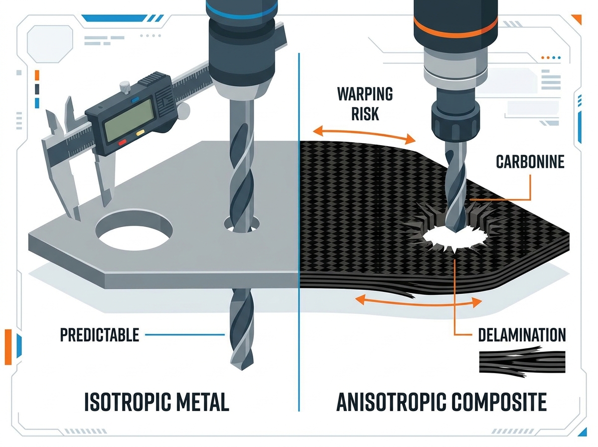
Composites possess a unique coefficient of thermal expansion (CTE). They expand and contract differently along the fiber axis compared to the resin matrix. When plates cure at high temperatures, internal stresses develop. If you cool an unbalanced plate, it warps.
You must mandate symmetric laminate designs in your RFQ. A symmetric schedule places equal layers at equal angles from the center plane. This natural engineering constraint allows the material to resist bending and torsion during cooling. For standard applications, an acceptable flatness tolerance is roughly 0.015 inches per foot. High-precision requirements demand post-cure grinding, which heavily increases costs.
Layer thickness directly dictates bending load limits. You cannot specify a random decimal thickness and expect an optimal part. Manufacturers build plates using discrete plies of prepreg carbon. Each ply adds a specific fraction of a millimeter.
You should specify a nominal thickness alongside acceptable positive and negative variations. The manufacturing method changes these variations. Autoclave curing provides high pressure, creating tightly consolidated plates with strict thickness control. Press molding often yields wider thickness variations. Always align your thickness tolerances with the chosen fabrication method.
Drilling carbon fiber presents severe machining challenges. The abrasive fibers destroy standard high-speed steel tools instantly. Tool wear leads directly to undersized holes. Plunging a drill bit through the plate also causes aggressive exit-side splintering.
To avoid these failures, you must specify robust machining practices. When designing CNC-finished custom carbon fiber parts, mandate interpolated milling instead of standard drilling. Interpolated milling uses a smaller endmill cutting in a circular path. This method gently shears the fibers and prevents delamination.
Outline realistic True Position (TP) callouts for mating parts. A True Position tolerance of 0.005 inches is achievable but requires strict thermal control during machining. For most composite-to-metal assemblies, a TP of 0.010 inches provides a reliable, cost-effective target.
The exterior finish of a composite plate dictates its functional compatibility. You cannot treat the surface as merely an aesthetic choice. You must define your carbon fiber surface finishes based on the actual end-use application.
If you plan to glue the plate to another structure, specify a peel-ply or matte finish. The peel-ply fabric tears away after curing. This leaves a micro-textured surface. Adhesives require this rough texture for mechanical interlocking. Conversely, specify a high-gloss finish for cosmetic applications. Gloss finishes often include specialized clear coats. These coatings provide critical UV resistance, preventing the underlying epoxy from yellowing over time.
Subjective specifications destroy quality control. Never use terms like "looks good" or "free of major defects." These phrases mean nothing to a machinist on the floor. You must establish strictly quantifiable limits.
Surface pinholes occur naturally due to trapped air during curing. Set an acceptable threshold. For example, mandate "no more than 3 pinholes greater than 0.5mm per square foot." You must also establish firm criteria for weave distortion. Carbon fabrics shift during placement. Define exactly how much fabric bridging is acceptable near plate edges.
Defect Type | Classification | Acceptable Threshold (Example) | Functional Impact |
|---|---|---|---|
Surface Pinholes | Cosmetic | < 3 per sq ft, max 0.5mm dia. | Aesthetic flaw; minor moisture trap. |
Weave Distortion | Cosmetic | Max 5° deviation over 12 inches | Visual misalignment; minimal strength loss. |
Internal Voids | Structural | < 2% total volume (via C-Scan) | Reduces interlaminar shear strength. |
Edge Delamination | Structural | Zero tolerance | Causes progressive mechanical failure. |
You must outline exact conditions for visual sign-off. First, define the terminology clearly. A "dry spot" indicates a localized lack of resin, leaving raw fibers exposed. A "resin-rich area" shows an excessive pooling of epoxy, which makes the part brittle. "Edge delamination" describes the visible separation of distinct carbon layers.
Next, specify the environment for visual inspection. Do not let vendors inspect parts under harsh, glaring spotlights or total shadows. Specify a standard viewing distance. A common industry standard dictates inspecting the plate from 18 inches away under standard fluorescent daylight.
High-stress applications require stringent testing. Outline clear non-destructive testing (NDT) expectations. For critical structural plates, mandate ultrasonic scanning. C-scans map the interior of the composite. They reveal hidden internal voids that visual inspections miss entirely.
Specify required mechanical baseline tests tailored to your operational environment. Require flexural strength tests, such as ASTM D790 three-point bending. If the plate experiences clamping forces, mandate localized compression testing. This verifies the crush characteristics of the laminate. These baseline tests confirm the part will survive real-world loading.
Accountability ensures long-term part safety. You must require formal documentation for every production batch. Demand a Certificate of Conformance (CoC). This document acts as a legal guarantee from the supplier. It certifies they followed the agreed-upon manufacturing process.
Furthermore, require Material Test Reports (MTR). You need traceable data for both the dry carbon fiber and the resin matrix. If a plate fails in the field five years later, MTRs allow you to identify the exact material batch responsible for the defect.
Not every machine shop can handle carbon composites. You must audit a potential supplier's specific composite capabilities. Ask direct questions about their tooling inventory. Do they use standard carbide endmills? If so, walk away. Quality vendors utilize diamond-coated or polycrystalline diamond (PCD) tooling exclusively. PCD tooling cleanly cuts through abrasive carbon without dulling or tearing the laminate.
You should also ask for historical capability data. Request case studies or inspection reports on plates with similar thicknesses and layup schedules. This proves they have solved thermal warping issues in the past.
Never rush into full-scale production. Phase the rollout carefully to protect your budget. You must specify a mandatory First Article Inspection (FAI) report. The supplier must measure and record all critical dimensions on the very first part. You review this FAI report before authorizing the remaining production run.
Clarify the exact remediation process in your contract. If a batch fails the defined acceptance criteria, what happens? Determine who pays for the scrapped material. Outline whether the vendor gets one chance to rework the parts or if you cancel the contract immediately. Clear risk mitigation prevents costly legal disputes.
Bridge the gap: Effective specification translates theoretical composite design into practical manufacturing reality.
Control the layup: Mandate symmetric laminate schedules to prevent thermal warping and ensure dimensional stability.
Specify machining methods: Require interpolated milling and PCD tooling to eliminate edge delamination.
Quantify aesthetics: Establish strict numerical limits for cosmetic defects instead of relying on subjective opinions.
Create standard documents: Consolidate your flatness, machining, and aesthetic requirements into a standardized RFQ document. Use this to evaluate potential manufacturing partners accurately before committing capital.
A: For standard commercial plates up to 0.25 inches thick, a realistic flatness tolerance is 0.015 inches per linear foot. Thinner plates may exhibit slightly more warp due to thermal stresses during curing. If you require tighter tolerances, you must specify precision-ground plates. This approach increases costs but ensures absolute flatness for highly sensitive mechanical assemblies.
A: Surface treatments directly impact overall plate thickness. A raw peel-ply finish leaves a textured surface that slightly reduces measurable thickness consistency. Alternatively, applying high-gloss clear coats adds unpredictable resin layers. This added material can push tightly toleranced plates out of spec. You should always define whether your dimensional tolerances apply before or after applying any surface coatings.
A: Edge delamination occurs when cutting tools pull the composite layers apart instead of shearing them. Standard drill bits lift the top fibers upon exit. You can prevent this by specifying interpolated milling and the use of hard backing boards during machining. Always require vendors to use polycrystalline diamond (PCD) tooling to ensure clean, delamination-free edges.
A: Yes, but it is rarely cost-effective. Specifying exact ply weights restricts the manufacturer from using standard, readily available prepreg rolls. Instead, you should specify the final finished part thickness along with an acceptable tolerance range. The manufacturer can then design a balanced laminate schedule that meets your mechanical requirements without inflating material procurement costs.


