
English 
+86-157-6313-9515
lina@hezongmaterials.com
lina@hezongmaterials.com
26 Jiashan Road, Chucun Town, Weihai City, Shandong Province, China


Views: 0 Author: Site Editor Publish Time: 2026-05-26 Origin: Site


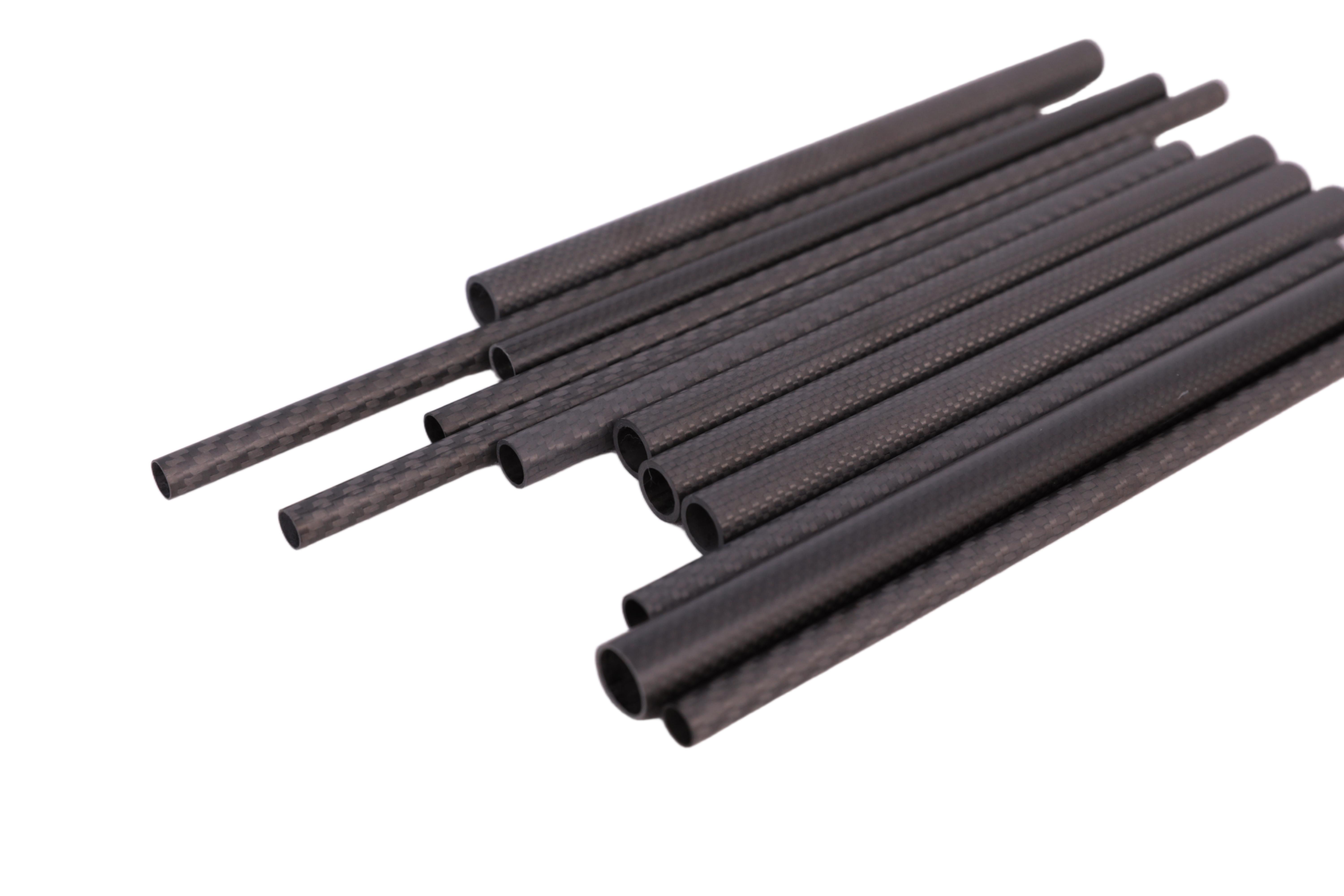
A critical ambiguity exists in material science today. Treating carbon fiber strictly as a conductor or an insulator leads to catastrophic engineering failures. Many design teams misunderstand how this advanced material interacts with electrical currents. You cannot simply drop it into a circuit model and expect standard behaviors.
The answer to its conductivity depends entirely on the material state. Raw fiber behaves very differently from a cured composite matrix. A dry spool of filament readily transmits energy. However, once you encase those same filaments in epoxy resin to create a structural component, the electrical properties change dramatically. The resin introduces complex insulating barriers.
This article serves as a technical evaluation guide. Engineering and procurement teams assessing materials for electronics, aerospace, or structural applications will learn how to navigate these complexities. You will discover how to harness the material's thermal benefits without compromising electrical safety.
Raw carbon fiber is electrically and thermally conductive, though significantly less efficient than metals like copper or aluminum.
In Carbon Fiber Reinforced Polymers (CFRP), the surrounding epoxy resin acts as an insulator, resulting in anisotropic (directional) conductivity.
Integrating carbon fiber with dissimilar metals (especially aluminum) introduces severe risks of galvanic corrosion if not properly isolated.
Machining carbon fiber creates highly conductive dust that poses a major short-circuit risk to nearby electronics and manufacturing equipment.
Engineers must first separate the raw material from the finished composite. You cannot accurately predict conductivity without understanding the microscopic structure of both phases. Let us examine the fundamental physics driving these behaviors.
Raw filaments possess a unique atomic structure. Manufacturers typically produce them from polyacrylonitrile (PAN) or petroleum pitch. During the high-temperature carbonization process, the internal atoms form tightly bonded, graphite-like crystalline networks. These sp2 carbon bonds create delocalized electron clouds. Electrons can move freely along these continuous molecular chains.
Because electrons mobilize easily, the raw filament conducts electricity. However, we must establish a baseline compared to traditional metals. Consider the volume resistivity ranges:
Copper: ~1.7 x 10⁻⁸ Ω·m (Highly conductive)
Aluminum: ~2.8 x 10⁻⁸ Ω·m (Highly conductive)
PAN-based Carbon Fiber: ~1.5 x 10⁻³ Ω·m (Moderately conductive)
Glass Fiber: >10¹² Ω·m (Insulator)
The data reveals a clear reality. The raw fiber conducts energy, but it offers substantially higher resistance than standard wiring metals. It acts as a poor conductor relative to copper, yet a brilliant conductor compared to fiberglass.
In real-world applications, you rarely use the raw filament. Instead, you work with Carbon Fiber Reinforced Polymers (CFRP). Creating CFRP involves infusing the woven or unidirectional filaments with a polymer matrix. Usually, this matrix consists of epoxy resin. Epoxy is a highly effective dielectric barrier. It strongly resists the flow of electrical current.
This combination creates anisotropic conductivity. Anisotropic means the material exhibits different properties depending on the direction of measurement. Electricity flows reasonably well along the longitudinal axis of the fibers. The continuous carbon chains provide an uninterrupted path. Conversely, current faces high resistance transversely. When electricity tries to jump from one fiber to another, it hits the insulating epoxy resin.
Relying on a composite panel as a primary electrical ground is a critical design flaw. You cannot guarantee a consistent longitudinal path. The resin distribution varies microscopically across the panel. Similarly, treating a CFRP enclosure as a strict insulator invites disaster. Surface scratches or drilled holes expose the conductive core filaments. You must demand rigorous testing rather than relying on dangerous assumptions.
Many procurement professionals confuse electrical and thermal pathways. A material can resist electricity while simultaneously transferring heat. Understanding this distinction unlocks major design advantages for engineering teams.
We know carbon fiber conducts electricity. However, it cannot replace standard wiring in high-current applications. The higher volume resistivity creates significant friction for moving electrons. This friction generates heat under electrical load.
If you push a high-amperage current through a composite rod, it will heat up rapidly. In extreme cases, the internal temperature will exceed the glass transition temperature of the epoxy. The resin will melt, degrade, and ultimately fail structurally. You must restrict CFRP to static dissipation or low-current signal transmission.
Thermal conductivity tells a very different story. Heat transfers through atomic vibrations (phonons) rather than electron mobility. Pitch-based filaments excel at this process. The highly aligned crystalline structure dissipates heat efficiently along the fiber axis.
Standard PAN-based composites offer moderate thermal conductivity. They typically range from 5 to 20 W/m·K. Pitch-based composites, however, can achieve thermal conductivities exceeding 500 W/m·K longitudinally. They often rival or exceed metals like aluminum (around 200 W/m·K) and copper (around 400 W/m·K).
| Material Type | Electrical Resistivity (Ω·m) | Thermal Conductivity (W/m·K) | Primary Design Use |
|---|---|---|---|
| Aluminum 6061 | ~3.9 x 10⁻⁸ | ~167 | Structural / Heat Sinks |
| Copper | ~1.7 x 10⁻⁸ | ~401 | Wiring / Electronics |
| PAN-based CFRP (Longitudinal) | ~1.5 x 10⁻³ | 5 - 20 | High Strength / Lightweighting |
| Pitch-based CFRP (Longitudinal) | ~2.5 x 10⁻³ | 500 - 900+ | Thermal Management / Aerospace |
How can engineering teams leverage these properties? Consider an electric vehicle (EV) battery enclosure. The battery cells generate massive amounts of heat. They also carry lethal electrical voltages. Engineers need a material that dissipates heat outward while maintaining electrical isolation to prevent short circuits.
By utilizing specific pitch-based layups and dielectric surface layers, teams solve both problems simultaneously. They shed the thermal load quickly. They drop significant weight compared to aluminum housings. They also maintain the necessary electrical isolation parameters.
Transitioning from traditional materials to advanced composites introduces hidden dangers. You must actively engineer solutions to prevent electrochemical degradation and facility hazards.
Galvanic corrosion represents the silent killer of mixed-material assemblies. This chemical reaction occurs when two dissimilar conductive materials make direct physical contact in the presence of an electrolyte. Moisture from ambient humidity often provides enough electrolytic action.
On the galvanic scale, graphite (carbon) acts as a highly noble, cathodic material. Aluminum and steel act as anodic materials. When you bolt an aluminum bracket directly to a CFRP panel, a battery cell forms. The aluminum sacrifices its electrons to the carbon. The aluminum bracket will rapidly corrode, pit, and eventually fail mechanically.
Engineers must implement standard mitigation solutions to prevent this:
Barrier Layers: Incorporate a lightweight fiberglass scrim layer between the carbon plies and the metal mating surface during layup.
Dielectric Coatings: Apply specialized epoxy primers or polyurethane topcoats to isolate the metal hardware.
Material Substitution: Swap aluminum fasteners for titanium fasteners. Titanium sits much closer to carbon on the galvanic scale, virtually eliminating the reaction.
The risks extend beyond the final product. Prototyping and production phases present severe environmental challenges. When you cut, drill, or sand a composite part, you generate microscopic dust. This airborne dust contains shattered, raw carbon filaments.
Because the raw filaments conduct electricity, the airborne dust poses a massive short-circuit hazard. If this dust settles on open circuitry, motherboards, or CNC machine controls, it bridges electrical contacts. The resulting short circuits destroy expensive manufacturing equipment.
Facilities must enforce strict compliance and safety protocols. You must isolate machining zones. Use HEPA-filtered vacuum extraction directly at the cutting tool. Protect facility HVAC systems with upgraded filtration to prevent conductive dust from circulating into administrative or server rooms.
Design teams and purchasing departments must align their goals. Procuring advanced composites requires a different framework than buying bulk metals. You must evaluate the holistic impact of the material on the entire assembly.
Define clearly when to choose this composite over aluminum or fiberglass. The decision hinges on the strength-to-weight ratio versus electrical isolation needs.
Choose composites when extreme stiffness and low mass dominate the project requirements. Aerospace wings, performance automotive chassis, and robotic arms fit this profile perfectly. If absolute electrical insulation is the primary goal and weight matters less, fiberglass offers a safer, cheaper alternative. If structural grounding is mandatory and weight is secondary, aluminum remains the superior choice.
Procurement teams often look only at the raw material price per kilogram. This narrow view ignores the hidden costs of integrating the material safely. You must factor in the mitigation realities.
You cannot use cheap steel or aluminum bolts. You must budget for expensive titanium fasteners or specialized coated hardware. You must purchase dielectric isolation adhesives. You need fiberglass barrier plies integrated into the manufacturing process. These necessary protective measures increase the final assembly cost. Evaluating carbon fiber demands a full-assembly perspective to avoid budget overruns late in the design cycle.
Do not accept generic specification sheets from suppliers. The anisotropic nature of the material requires precise data. Use a rigorous assessment framework when interviewing composite vendors.
| Evaluation Area | Questions to Ask Suppliers | Expected Documentation |
|---|---|---|
| Resin Matrix Properties | What specific epoxy formulation are you using? What is its baseline dielectric strength? | Technical Data Sheet (TDS) for the pure resin system. |
| Fiber Alignment & Layup | How does the ply orientation affect transverse electrical resistance in this specific part? | Laminate analysis report detailing longitudinal and transverse metrics. |
| Standardized Testing | Have you tested this exact layup configuration for dielectric breakdown? | ASTM D149 (Dielectric Breakdown) or ASTM D257 (DC Resistance) test results. |
Demand transparency. Ask for batch-tested conductivity metrics. A reputable supplier will understand the nuances of composite electrical behavior. They should provide test results for your specific layup, rather than relying on theoretical data.
Even experienced engineers harbor misconceptions about composite materials. Erasing these myths prevents dangerous design choices and costly product recalls.
Fact: The resin encapsulating the filaments is plastic. It provides a temporary dielectric barrier. However, structural wear, aggressive drilling, or physical impact exposes the highly conductive core fibers. If an insulated wire chafes against a bare composite edge, it will eventually cut through the epoxy. Once it touches the raw filaments, current will arc, creating a severe shock hazard.
Fact: You cannot trust a standard composite panel for critical grounding. The resistance across the matrix fluctuates wildly. Resin-rich areas block the current. Fiber-rich areas transmit it. This inconsistent resistance makes it an unreliable and highly unsafe primary grounding path. Aerospace engineers solve this by integrating a physical metal mesh—typically copper or bronze—into the surface ply. The embedded metal handles the grounding path, not the composite itself.
The electrical properties of advanced composites require careful navigation. We must abandon the binary idea of "conductor versus insulator." The material exists on a complex spectrum dictated by its precursor, matrix, and structural layup.
By understanding anisotropic conductivity, you prevent dangerous grounding assumptions. By respecting galvanic corrosion, you ensure long-term structural integrity. Carbon fiber's conductivity is a manageable characteristic, not an automatic disqualifier. Provided the engineering design accounts for galvanic and anisotropic realities, you can leverage its massive strength-to-weight benefits safely.
Your next steps should focus on physical validation. Recommend initiating physical prototyping with specific resin-to-fiber ratios. Conduct rigorous dielectric breakdown testing (via ASTM standards) on the actual manufactured parts before finalizing any material procurement. Trust engineered test data over theoretical assumptions.
A: Yes, it attenuates radio frequencies and electromagnetic interference (EMI). The conductive network within the composite absorbs and reflects electromagnetic waves. This requires careful consideration for internal antennas, as they cannot transmit efficiently through a CFRP enclosure without specialized cutouts or externally mounted receivers.
A: No, carbon fiber is entirely non-magnetic. It contains no ferrous metals. This property makes it highly suitable for medical imaging environments. Manufacturers frequently use it to build MRI machine beds and structural components where magnetic interference would disrupt sensitive diagnostic equipment.
A: Yes. A lightning strike delivers massive electrical current. Because CFRP has high electrical resistance, the current generates extreme heat instantly. This vaporizes the epoxy resin and causes explosive structural failure. Aerospace engineers mitigate this by embedding a conductive mesh (like copper or aluminum foil) into the outer layers to dissipate the strike energy.


